


DEPUTY GENERAL MANAGER
The Fuji Electric company has developed the 7th Generation X series IPM and IGBTs for the inverter industry, offering smaller sizes, reduced losses and increased performance. Utilizing the 7th generation X series chip and control integrations, a 10% reduction in losses compared to previous models was achieved, allowing the product to operate continuously at 150°C. Thanks to this, the output current of the device has also been increased by %31. Apart from the conventional protection functions, the built-in temperature warning function eliminates the risk of inverters stopping. Also, when the short arm protection is activated, the braking IGBT can be operated independently to prevent semiconductor devices from being damaged by high voltage. The ability of the products developed today, where the need for energy is increasing, to run with higher power and less energy is an essential aspect that every sector should take into account. Fuji Electric has become an industry-leading company in the semiconductor products field it has developed over the years. Fuji Electric has introduced its new series with 7th generation products in IGBT and IPM families, which are among the most important products in inverter sector, with higher performance, reduced losses and minimized dimensions.
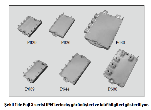
In line with the need for small-sized products in inverter market, Fuji is now launching products in three new cases: P639, P638 and P644. With these products, which are added to the existing 5 different cases, the family is now further expanding. The P639 has been downsized by 27% compared to P629. The P644 family is available in the same case with P626, but as a 7-IGBT variant. The P644 family offers the same current capacity as the P638 family with a 54% smaller size.
Devices with high current capacity need materials that provide high thermal conductivity in order to be able to transfer the heat quickly. Fuji, with its X series IPMs, also allowed for the high current and high voltage products needed by the industry. While the V series IGBTs offer a solution of up to 400 amperes at 600 volts and 200 amperes at 1200 volts, these values have been increased to 450 amperes at 600 volts and 300 amperes at 1200 volts in the X series. In this way, a significant downsizing can be achieved in the new generation devices.
Using new generation chip and control integrations in the X series enabled a 7% reduction in losses compared to the previous V series. The device started working at a higher temperature as the operating temperature is increased from 125°C to 150°C. X series provides a 31% increase in output current compared to V series.
The X series is also the first device in the industry to offer a temperature warning function as a protector. In this way, the user can understand from the alarm that the IGBT is overheating, which not only shortens the emergency stop times of the device but also supports the effective use of the device.
“The X series IPMs also feature a new alarm output function that allows the low arm protection instant braking IGBT to operate alone.”
General Function and Features
It is essential to reduce the losses of IPM in order to increase the overall efficiency of power inverter devices. The determining factors in these losses are the semiconductor chip used in the mIPiMttedre, the release diodes and the control circuits used to drive this IGBT.
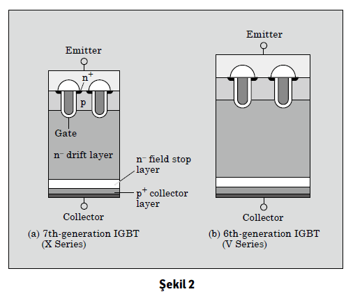
Figure 2 shows the cross-section of the IGBT chips. In addition to the trench gate structure in the 7th and 6th generation IGBTs, a thin film IGBT with a field stop layer on the back surface is also used. Compared to the 6th generation, the 7th generation IGBTs have improved collector-emitter scattering voltage and reduced turn-off losses by reducing the chip thickness.
(Intelligent power modules) IPMs provide more surface optimization than IGBTs. A specific improvement has been developed for these IPMS thanks to the integrated short circuit protection function. In this way, the 7th generation IGBT-IPMs require 0.15 to 0.25 volts less switching voltage when compared to the 6th generation, at same turn-off losses.
Since the surface is minimized, decreasing voltage voltages may lead to an increase in short-circuit currents. Therefore, the trade-off feature has been improved by accelerating short-circuit protection. As a result, the X series IPMs provides support with the switching sliding current function to reduce turn-on losses during switching. With this function, it is now possible to drive the IGBT with a higher current at high temperatures and reduce switching losses. Moreover, since the IGBT chip temperatures are monitored in real time, switching can be carried out at the optimum time. The sliding current value has also been optimized, preventing the possibility of trade-off switching losses increasing noise.
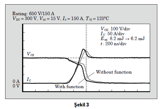
Figure 3 shows the reduction of turn-on losses in the IGBT gate drive circuit thanks to the sliding current function. This function has resulted in a 24% reduction in trip losses.
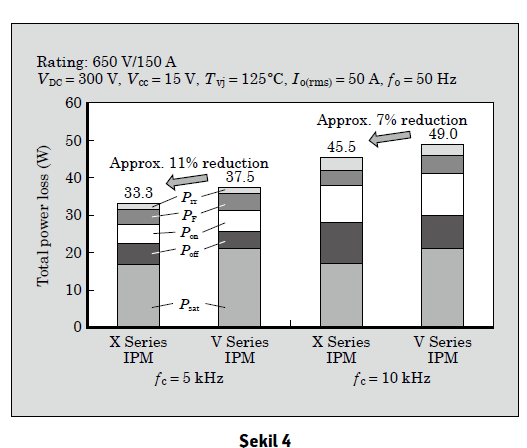
Figure 4 shows the simulation of power losses in the inverter application of IPM to 650 volts /150. As can be seen in the figure, the power dissipation is improved by about 11% at 5 kHz and 7% at 10 kHz compared to V series IPM.
Features of Protection Function
Table 1 shows a comparison of X series IPMS with conventional V series IPMS. The features of X series IPMs include high speed short-circuit protection function, enhanced alarm output function, internal temperature warning output function and independent braking during alarm.
As detailed in Section 3.1, minimizing the surface structure of IGBT chips improve IGBT comparisons and maximize chip performance. However, since the short-circuit current level on the IGBT chip has increased, it is necessary to speed up the short-circuit protection function without incorrect increases. Therefore, in addition to accelerating the suppression of peak currents that occur in short-circuit currents, the shutdown delay time has also been optimized “to prevent failures that may occur due to incorrect increases”.
In addition, the X series IPMs use the industry’s first alarm-cause detection function, which extends the interval of identifying each alarm cause from 0.1ms to 1.1 ms. Thus, the identifiability of the alarm-cause identification function increases.
The X series IPMs also feature a new alarm output function that allows the low arm protection instant braking IGBT to operate alone.
In traditional IPMS, the alarm output circuit algorithm, which occurs when an abnormal condition is detected in the low arm, is activated and all short arm operations are stopped. In this case, braking IGBT will also stop. This will prevent formation of regenerated energy from the rotating motor of the braking circuit and cause the P_N voltage to increase.
In X series IPMS, the braking IGBT can continue to work in the event of an incorrect output caused by an abnormal condition that will occur in the short arm. Thus, X series IPMS can eliminate this issue. In addition, this suppresses the increase in P_N voltage caused by the power regeneration from the motor in the main power supply and prevents the breakdown of semiconductor devices from overvoltage. Moreover, when there is an abnormality in the braking IGBT, the braking IGBT and the inverters on the other low arm are protected as usual.
3.3 Temperature Warning Output Function
(Can be applied in some models.) The X series IPMs are the first IPMs in the industry with a temperature alarm output function.
This output function displays the temperature on the IGBT chip and provides IPM users with an alarm about the over-temperature status of the chip when the temperature exceeds the set limit values.
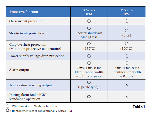
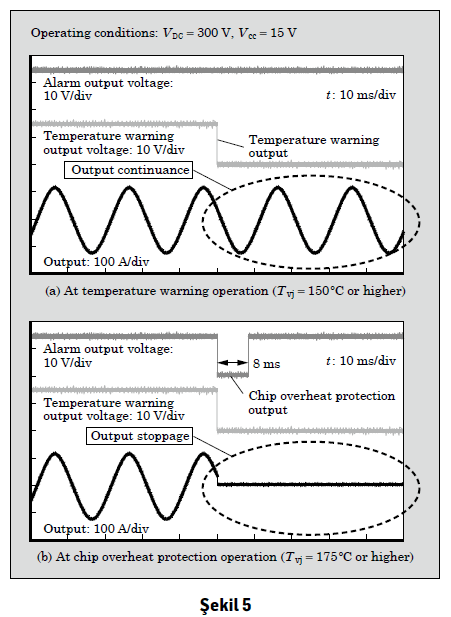
Figure 5 shows the waveforms of the temperature warning output function during operation. The chip over-temperature protection function is used to set an alarm and stop the switching process when the chip temperature of the IGBT exceeds 175°C. On the other hand, the temperature warning output function ensures that the switching process of the IGBT continues while the temperature warning is given. This especially applies when there is a cooling failure in devices such as a machine tool or elevator (wing blockage, fan failure, etc.) The IGBT chip inside the X series IPMs will issue a temperature warning signal when the temperature exceeds 150°C. The equipment receiving the signal prevents stalling by reducing the load current applied to the IPM, preventing the IGBT chip temperature from exceeding 175°C. In this way, the work continues and the repair of the device can be carried out at a convenient time.
4. The Effect of Reducing High Temperature Losses
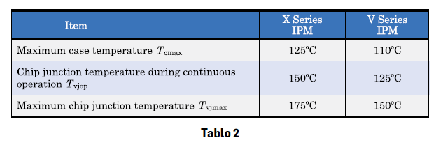
Table 2 shows the operating temperature comparison between X series and V series IPMs.
In X series IPMs, when compared to the V series IPMs, the Tvjop value has been increased from 125°C to 150°C and the maximum chip temperature from 150°C to 175°C.
Tvjop: (Chip junction temperature during operation)
Tcmax (Maximum case temperature)
Tvjmax (Maximum chip junction temperature)
High temperature operation is possible thanks to the high temperature resistant gel and high reliability solder features in the 7th generation packaging technology of the X series IPMs. Also, the control integration in the IPM makes it possible to work at high temperatures by applying a layout design that takes into account high temperature and a circuit design that is not sensitive to electro-migration. As a result, it can be applied under heavier load conditions and in power conversion equipment with lower heat dissipation.
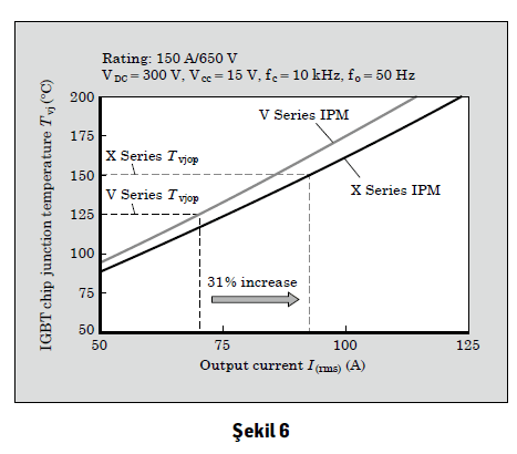
Figure 6 shows a comparison of the inventor output current and chip junction temperature when the IPM is connected to the inventor, which acts as a power conversion element. X series IPMs, when compared to V series IPMs, can increase the output current by 31% by increasing the IGBT chip junction temperature during continuous operation and reducing power losses.