In electronic circuits, the circuit elements used to protect the board and components against excessive current, voltage, heat or other damaging conditions are called circuit protection components. These components that have various types such as varistors, thermostats, gas discharge tubes, fuses, thermistors, etc. are critical components for electronic circuits.
Types of Circuit Protection Components
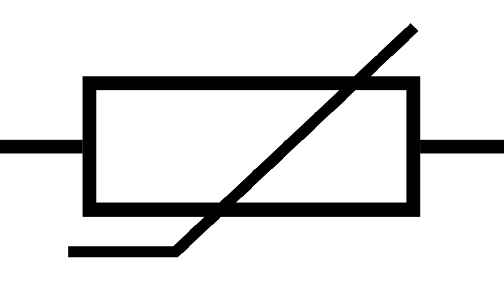
Varistor
A varistor is a circuit element used in electrical circuits to provide protection against overvoltage.
Structure:
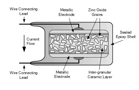
- Varistors are manufactured by pressing the substances such as Zinc Oxide (ZnO), Titanium Dioxide (TiO2 ) or Silicon Carbide(SiC), usually in the form of a disc or cylinder, into a mold.
- The molded varistor is sintered at high temperature. The sintering process allows the metal oxide grains to bond together and the varistor to become stable.
- The varistor is covered with a protective coating and its installation is completed.

Operating Principle:
- At a Normal Voltage Level: As long as the voltage in the electrical circuit is within the normal operating range of the varistor, the resistance of the varistor is very high. With this high resistance, the varistor makes minimal impact on the circuit and there is no energy loss.
- At a High Voltage Level: When the voltage exceeds the nominal degrees, the resistance of the varistor decreases. This prevents the device from being damaged by overvoltage.
Types:
- Metal Oxide Varistor (MOV): It is a type of varistor that is widely used to provide protection against overvoltage. Its ceramic structure usually consists of zinc oxide particles. It may also contain bismuth and cobalt when necessary.
- Silicon Carbide Varistor (SiC): These are the semiconductor elements used in overvoltage protection. They work in a similar way to metal oxide varistors (MOVS), while they have some specific advantages and disadvantages. The major advantages are that SiC varistors can self-recover in case of a malfunction. In this way, they do not short the circuit and ensure the safety and continuity of the circuit. The disadvantages, on the other hand, include significant standby current draws, high cost and manufacturing difficulties.
Mode of Use in the Circuit:
- A varistor is used, in energy systems, by connecting in parallel between the AC voltage source and voltage-sensitive receiver circuits.

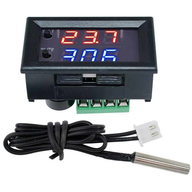
Thermostat
Circuit protective thermostats are the circuit elements used to provide temperature control in electrical and electronic devices. Its main function is to control the electric current based on the desired temperature.
Structure:
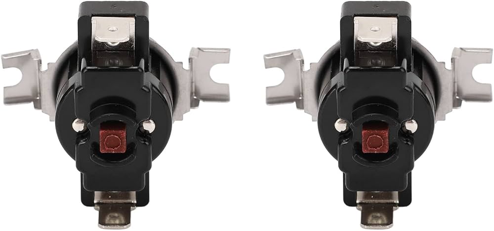
A thermostat consists of a sensor, a control mechanism and an output device that detects the temperature. The sensor is usually made of materials such as a thermal bimetal or thermistor. The control mechanism processes the information received from the sensor and activates or deactivates the output device (a relay or transistor) when a set temperature threshold is reached.
Example:
- Bimetallic Strip: This strip, consisting of two different metals, bends as a response to temperature changes. It consists of a combination of two metals. These metals have different coefficients of expansion, and thanks to this, one stretches or bends more than the other.
- Contacts: These are the electrical contacts that open or close based on the bimetallic strip.
- Housing: This is a case that protects the internal components of the thermostat and provides endurance against environmental conditions.

Operating Principle:
The operating principle of a thermostat is usually based on physical effects, such as thermal expansion or a change in electrical resistance.
Example:
- Normal Temperature Condition: When the device is operating at a normal temperature, the strip remains flat and the contacts are closed.
- High Temperature Condition: As the temperature of the device increases, the bimetallic strip expands and bends, and the contacts are opened. In such a case, it prevents the device from heating up by cutting off the electrical current.
- Cooling State: When the device cools down, the bimetallic strip returns to its original state and the contact closes.
Types:
- Mechanical Thermostat: It controls the temperature using mechanical principles such as thermal expansion or mechanical contacts.
1. Bimetallic Strip Thermostats
2. Liquid Filled Thermostats - Electronic Thermostat: It carries out temperature control using electronic components and sensors.
1. Digital Thermostats
2. Programmable Thermostats
3. Smart Thermostats - Hybrid Thermostat
- Line Voltage Thermostat
- Low Voltage Thermostat
- Pneumatic Thermostat
Thyristor Voltage Protectors
Thyristor voltage protectors are the semiconductor components used to protect electrical circuits and devices against sudden voltage spikes or surges. Thyristors are widely used in protection circuits due to their fast response time at high current and voltage values.
GDT-Gas Discharge Tubes
Gas discharge tubes are the circuit elements used to protect electrical circuits against overvoltage. These circuit elements become conductive when they reach a certain voltage level and protect the devices by discharging excess voltage to the ground. They are widely used in applications such as telephone lines, communication systems and power distribution systems.

Structure:
- Tube: It is made of a cylindrical glass or ceramic tube and contains gas inside.
- Electrodes: They are the metal electrodes located at the two ends of the tube and transmit electric current during gas discharge.
- Gas: Gas, which normally provides an insulating environment, ionizes and becomes conductive when the voltage exceeds a certain level.
Operating Principle:
- Normal Condition: Under normal operating conditions, the gas inside the tube acts as an insulator and no current passes between the electrodes.
- Overvoltage Condition: When the voltage exceeds a set threshold, the gas ionizes and the current begins to flow between the electrodes. The overvoltage is directed to the earth by flowing between the electrons.
Types:
- Standard Gas Discharge Tube: It is used for overvoltage protection, particularly in communication lines and electrical distribution systems.
- High Energy Gas Discharge Tube: It provides protection against high energy discharges.
- Multi-Electrode Gas Discharge Tube: It contains three or more electrodes. It is used in applications that require multi-line protection.
- Low-Capacity Gas Discharge Tube: It is used in sensitive electronic devices to provide protection by reacting quickly at low capacities.
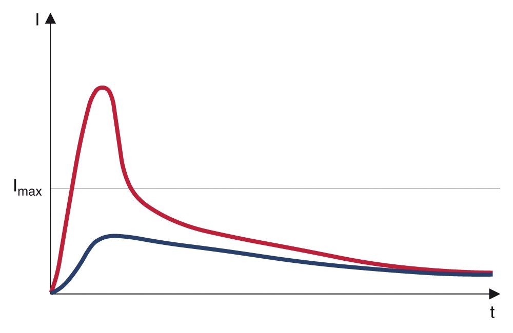
Inrush Current Limiters
Inrush current limiters are the electrical circuit elements used to limit sudden current fluctuations in electrical circuits.
Operating Principle:
- The current is controlled by adding a high-power resistor to the circuit at the beginning. The resistance is deactivated after the inrush currents and the initial currents drop.
Types:
- Constant Value Inrush Currents: A high-power resistor is added to the circuit initially and deactivated when it approaches the normal state.
- Time-Delayed Inrush Currents: The initial currents of the circuit are limited and switching to normal current is ensured. These circuit elements are often used in time relays and electronic timers.
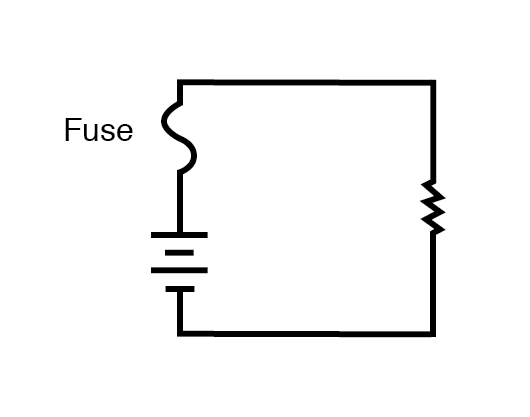
Fuse Components
Fuses are the circuit elements used to protect electrical circuits against excessive currents. When the current exceeds a set value, the fuse turns on the circuit, interrupts the current and prevents damage to the circuit elements and receivers connected to the circuit.
Structure:
- Fuse Element (Wire): It consists of a wire or strip with a low melting point, and the current flows through this strip/wire. Generally, lead, tin or copper are available in the wire’s structure.
- Fuse Body: It is a body structure consisting of an insulating material that protects the fuse wire. This body structure usually consists of glass, ceramic or plastic.
- Terminals: These are the points that allow the fuse to be connected to the circuit.
Operating Principle:
When the electric current exceeds a set level, the wire within the circuit is broken due to the melting of the wire in the fuse, and the current is cut off.
- Normal Operating Condition: The current flows through the fuse wire, but the wire does not reach the melting temperature.
- Overcurrent Condition: Since the current is above the rated current value of the fuse, the fuse wire excessively heats up and melts. When the wire melts, it opens the circuit and the current flow is interrupted.
- Protection Condition: Protects the circuit elements and devices against damage that may occur due to excessive current.
Types:
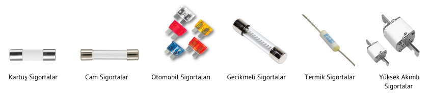
- Cartridge Fuses: They are the types of fuses with a cylindrical body. They are generally used in household and industrial applications.
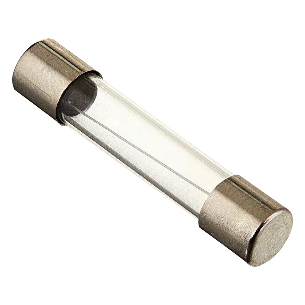
- Glass Tube Fuses: They are the fuses with glass bodies. They are mainly used in electronic devices and small electrical appliances.
- Automotive Fuses: They are used to protect the vehicle electrical systems. They are blade type fuses.
- Time-Delay Fuses: They temporarily tolerates the currents, and after a while the wire melts. They are used in devices that draw a high current at start, such as motors and transformers.
- Thermal Fuses: They provide protection against high temperatures. They are used in industrial electrical systems/devices.
- High Current Fuses (HRC): They are designed for circuits with high current capacity.
Mode of Use in the Circuit:
- The fuses are connected in series with the circuit elements that they are intended to protect. In this way, the current flowing through the fuse also flows through the protected device or circuit element. They are usually placed on the phase side of the circuit, which allows them to quickly keep the circuit under control.
Thermistors
Thermistors are temperature sensitive resistance elements. The values of resistance against temperature changes significantly. “Therm” refers to thermal and “Resistor” refers to resistance. They are used in the circuits that can be adjusted according to the change in temperature.
Structure:
- Ceramic Material: Thermistors containing ceramics in their structure contain components such as nickel, manganese and copper. They work at high temperatures and wide temperature ranges.
- Metal Electrodes: There are two “legs” depending on the ceramic material. These legs allow the resistance in the circuit to be measured.
- Coating: They are covered with coating materials such as epoxy and glass to protect the thermistor against external factors.

Operating Principle:
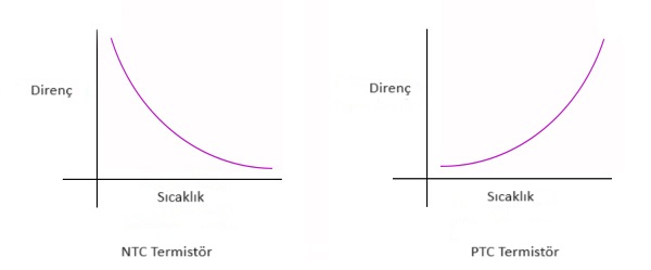
Thermistors are circuit elements that operate based on the resistance values that change depending on the temperature. They have two main types.
- Thermistors with Negative Temperature Coefficient (NTC): They operate inversely proportional to the temperature value. As the temperature increases, the resistance decreases.
– They are used in extreme temperature protection circuits and temperature circuits. - Thermistors with Positive Temperature Coefficient (PTC): They operate directly proportional to the temperature value.
– They are used in overcurrent protection circuits.