


You most probably have watched in documentaries the most important ability of chameleons: Camouflaging itself by adopting the color of the surface it touches. Taking these natural abilities as an example, we will develop a lamp that takes the color of the floor where it is placed, by using the Arduino and a color recognition sensor.

Our project consists of three parts;
- A sensor module that will detect the color of the floor and encode it for us
- The main unit that reads and processes the coding from the sensor module and transmits it
- A lighting module that will produce color based on the coding transmitted by the main unit
Now, let’s get to know the materials we will use;
1 – Color Recognition Sensor TCS230 Module
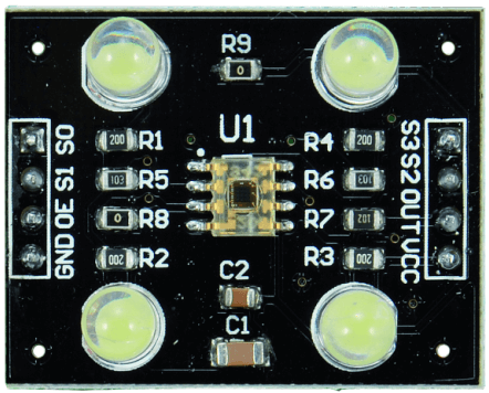
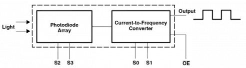
The TCS230 is a color detection module. This module contains a sensor that can detect different colors. It is generally used when developing projects with micro-controllers. The TCS230 can detect red, blue, green and white lights and transmit them to micro-controllers or other electronic devices.
2-Arduino Uno

3-RGB LED
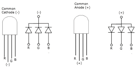
There are two types of RGB LEDs: ”common anode“ and ”common cathode”. In the first configuration, all LEDs have a common anode (i.e. their positive terminal), while the three LEDs are controlled separately by operating the cathode terminal of each. In the ”common cathode” components, three LEDs share a negative terminal, and each LED is powered using the anode, which is the positive terminal. The second, on the other hand, is a configuration that is more suitable for use with Arduino Uno.
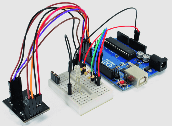
Circuit Diagram
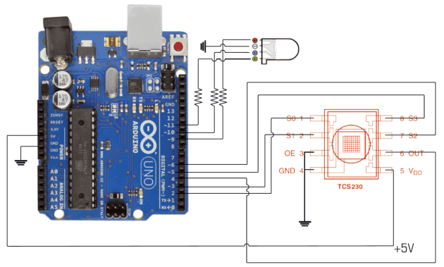
In the diagram you can see the connections between the Arduino micro-controller with TCS230 sensor and the RGB LED.
Code Structure
We will use the Serial Monitor to display the readings and the results of the calculations performed. We will configure the S0 and S1 pins correctly to turn the LEDs on and off. If the lamp is standing on a surface, we will measure both the total intensity of the reflected light and the relative intensities of the individual color components by applying the appropriate filter configuration to each reading via TCS230 pins S2 and S3. The relative intensity of each component is calculated according to the total color intensity read without any filter. To read the emitted frequency corresponding to the application of each filter, the “pulsein” command is used, which reads the pulse length on a given pin. The command can be configured to read the pulse duration at a LOW or HIGH level in our case. In this case, the command waits until the pin level receives the LOW value and starts the measurement time until the level returns to HIGH, and then interrupts the measurement. The result of the reading is in microseconds.
int S0 = 2; // output frequency control pin
int S1 = 3; // input frequency control pin
int S2 = 6; // pin color filter control
int S3 = 5; // pin color filter control
int taosOutPin = 4; // pin output for PWM
int LED = 13; // pinD
int R = 9; // PWM red
int G = 10; // PWM green
int B = 11; // PWM blue
double Coeff = 0;
int Ro = 0; // pin E
int Go = 0; // pin E
int Bo = 0; // pin E
void setup() {
TCS230setup();
Serial.begin(115200);
Serial.print(“\n\n\nready\n\n\n”);
pinMode(R,OUTPUT); //S2 pinE
pinMode(G,OUTPUT); //S2 pinE
pinMode(B,OUTPUT); //S2 pinE
delay(100);
}
void loop() {
Serial.print(detectColor(taosOutPin)); // serial debug
Serial.print(“\n\n\n”);
delay(1000);
}
int detectColor(int taosOutPin){
// surface detection
double isPresentTolerance = 5;
double isPresent = colorRead(taosOutPin,0,0)/colorRead(taosOutPin,0,1);
Serial.print(“isPresent:”);
Serial.println(isPresent,2);
Serial.print(“valore isPresentTolerance:”);
Serial.println(isPresentTolerance,2);
if(isPresent < isPresentTolerance){
Serial.println(“nessuna superficie rilevata”);
return 0;
}
double red,blue,green;
// light intensity detection no filters
double white = colorRead(taosOutPin,0,1);
// red
red = white/colorRead(taosOutPin,1,1);
// blue
blue = white/colorRead(taosOutPin,2,1);
// green
green = white/colorRead(taosOutPin,3,1);
Serial.print(“red”);
Serial.println(red);
Serial.print(“blue”);
Serial.println(blue);
Serial.print(“green”);
Serial.println(green);
if(red > blue && red > green)
Coeff = 255 / red;
Ro = 255;
Go = green * Coeff;
Bo = blue * Coeff;
LED_RGB(Ro, Go, Bo);
return 1;
}
if(blue > green && blue > red){
Coeff = 255 / blue;
Bo = 255;
Go = green * Coeff;
Ro = red * Coeff;
LED_RGB(Ro, Go, Bo);
return 2;
}
if(green > blue && green > red){
Coeff = 255 / green;
Go = 255;
Ro = red * Coeff;
Bo = blue * Coeff;
LED_RGB(Ro, Go, Bo);
return 3;
}
}
double colorRead(int taosOutPin, int color, boolean LEDstate){
//make sure that the pin is set to input
pinMode(taosOutPin, INPUT);
taosMode(1);
int sensorDelay = 3;
//set pins to trigger filters
if(color == 0){// bianco (no filtri)
digitalWrite(S3, LOW); //S3
digitalWrite(S2, HIGH); //S2
// Serial.print(” w”);
}else if(color == 1){// red filter
digitalWrite(S3, LOW); //S3
digitalWrite(S2, LOW); //S2
// Serial.print(” r”);
}else if(color == 2){// blue filter
digitalWrite(S3, HIGH); //S3
digitalWrite(S2, LOW); //S2
// Serial.print(” b”);
}else if(color == 3){// green filter
digitalWrite(S3, HIGH); //S3
digitalWrite(S2, HIGH); //S2
// Serial.print(” g”);
}
double readPulse
if(LEDstate == 0){
taosMode(0);
// digitalWrite(LED, LOW);
}
if(LEDstate == 1){
taosMode(1);
// digitalWrite(LED, HIGH);
}
delay(sensorDelay);
readPulse = pulseIn(taosOutPin, LOW, 80000);
// pulse timeout read setting
if(readPulse < .1){
readPulse = 80000;
}
// turn off sensor led
taosMode(0);
return readPulse;
}
// manages the frequency output mode TaosMode(0);
// sero, sensor quiet
void taosMode(int mode){
if(mode == 0){
//power OFF
digitalWrite(LED, LOW);
digitalWrite(S0, LOW); //S0
digitalWrite(S1, LOW); //S1
// Serial.println(“mOFFm”);
}else if(mode == 1){
// frequenza 1:1
digitalWrite(S0, HIGH); //S0
digitalWrite(S1, HIGH); //S1
// Serial.println(“m1:1m”);
}else if(mode == 2){
// frequenza 1:5
digitalWrite(S0, HIGH); //S
digitalWrite(S1, LOW); //S1
//Serial.println(“m1:5m”);
}else if(mode == 3){
// frequenza 1:50
digitalWrite(S0, LOW); //S0
digitalWrite(S1, HIGH); //S1
//Serial.println(“m1:50m”);
}
return
void LED_RGB(int Rx, int Gx, int Bx){
analogWrite(R, Rx);
analogWrite(G, Gx);
analogWrite(B, Bx);
return;
}
void TCS230setup(){
// init pin frequency management
pinMode(LED,OUTPUT);
// color filter management pin
pinMode(S2,OUTPUT); //S2
pinMode(S3,OUTPUT); //s3
// output pin light-frequency conversion
pinMode(taosOutPin, INPUT);
// pin to select ouput mode
pinMode(S0,OUTPUT); //S0 pinB
pinMode(S1,OUTPUT); //S1 pinA
return;
}