


What is a Flip Flop?
Flip-Flops (FF) are memory elements in digital electronic circuits having two stable states. They are used for functions such as binary data storage, counting and synchronization. They change their output state based on the signals applied to their inputs and maintain this state.

Working Principle of Flip-Flops
Flip-Flop circuits work depending on input signals and clock signals. Though the working principle of each type of Flip-Flop is different, Flip-Flops in general can be in two stable states and certain input combinations change these states. The working principles of RS, JK, D and T Flip-Flop circuits are as follows:
RS Flip-Flops
RS (Set-Reset) Flip-Flop is one of the basic memory elements used in digital electronic circuits. RS Flip-Flop is a circuit that has two stable states and is controlled by two inputs (Set and Reset). The purpose of RS Flip-Flop is to make the output 1 (Set) with the signal given to the Set input, and to make the output 0 (Reset) with the signal given to the Reset input.

Working Principle of RS Flip-Flop
Inputs and Outputs
Inputs:
S (Set)
R (Reset)
Outputs:
Q
!Q (Inverse of Q)
| S (Set) | R (Reset) | Q (Next State) | !Q (Next State) |
| 0 | 0 | Q | !Q |
| 0 | 1 | 0 | 1 |
| 1 | 0 | 1 | 0 |
| 1 | 1 | Belirsiz | Belirsiz |
Uygulama Alanları
RS Flip-Floplar, çeşitli dijital devrelerde temel yapı taşları olarak kullanılırlar. Bazı yaygın uygulamaları şunlardır:
- Veri Saklama: Basit bellek elemanları olarak kullanılır.
- Senkronizasyon: Çeşitli dijital devrelerde sinyal senkronizasyonu sağlar.
- Durum Takibi: Devrelerin belirli durumlarını takip etmek ve kontrol etmek için kullanılır.
JK Flip-Flop
JK Flip-Flop, dijital elektronik devrelerde kullanılan ve en yaygın türlerden biri olan bir Flip-Flop çeşididir. JK Flip-Flop, RS Flip-Flop’un geliştirilmiş bir versiyonudur ve RS Flip-Flop’un belirsiz durum problemini çözmek için tasarlanmıştır. JK Flip-Flop, Set (J) ve Reset (K) girişleri ile çalışır ve ayrıca clock sinyaline bağlıdır.
JK Flip-Flop’un Çalışma Prensibi
Girişler ve Çıkışlar
Girişler:
J (Set)
K (Reset)
CLK (Clock)
Çıkışlar:
Q
!Q (Q’nun tersi)
| J ( SET) | K (RESET) | CLK (Clock) | Q (Next State) | !Q(Next State) |
| 0 | 0 | ↑ | Q | !Q |
| 0 | 1 | ↑ | 0 | 1 |
| 1 | 0 | ↑ | 1 | 0 |
| 1 | 1 | ↑ | !Q | Q |
- S = 0, R = 0: The output state does not change, it maintains the previous state (Q and !Q).
- S = 0, R = 1: Q = 0, !Q = 1 (Reset state).
- S = 1, R = 0: Q = 1, !Q = 0 (Set state).
- S = 1, R = 1: Uncertainty case (forbidden) as this combination of inputs causes conflicting results at the outputs.
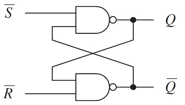
Internal Structure of RS Flip-Flop
RS Flip-Flop is usually constructed using two NOR gates or two NAND gates. Both structures are widely used.
Working Stages
1. Initial State:
- When both inputs (S and R) are 0, the outputs Q and !Q retain the previous state of the Flip-Flop.
2. Set State (S=1, R=0):
- When input S is 1, the output of the first NOR gate is 0.
- As the second NOR gate’s R input is 0 and the first NOR gate’s output is 0, the output is 1.
- In this case Q = 1, !Q = 0.
3. Reset State (S=0, R=1):
- When input R is 1, the output of the second NOR gate is 0.
- As the first NOR gate’s S input is 0 and the second NOR gate’s output is 0, the output is 1.
- In this case Q = 0, !Q = 1.
4. Both inputs 1 (S=1, R=1):
In this case, the output of both NOR gates becomes 0, which is an uncertain situation and should be avoided.
Areas of Application
RS Flip-Flops are used as basic building blocks in various digital circuits. Some applications they are commonly used in are:
- Data Storage: They are used as simple memory elements.
- Synchronization: They provide the synchronization of signals in various digital circuits.
- State Tracking: They are used to monitor and control certain states of circuits.
JK Flip-Flops
JK Flip-Flop is the most common type of Flip-Flops that is used in digital electronic circuits. JK Flip-Flop, an improved version of RS Flip-Flop, is designed to solve the uncertain state problem of RS Flip-Flop. JK Flip-Flop works with Set (J) and Reset (K) inputs and is also connected to the clock signal.
Working Principle of JK Flip-Flop
Inputs and Outputs
Inputs:
J (Set)
K (Reset)
CLK (Clock)
Outputs:
Q
!Q (Inverse of Q)
| Clock | D (Data) | Q (Next State) | !Q (Next State) |
| ↑ | 0 | 0 | 1 |
| ↑ | 1 | 1 | 0 |
- J = 0, K = 0: The output state does not change, it maintains the previous state (No Change).
- J = 0, K = 1: Q = 0, !Q = 1 (Reset).
- J = 1, K = 0: Q = 1, !Q = 0 (Set).
- J = 1, K = 1: The output state changes (toggle), so Q = !Q and !Q = Q.
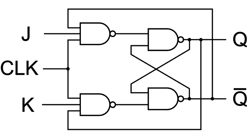
Internal Structure of JK Flip-Flop
JK Flip-Flop is usually constituted using two SR Flip-Flops and some logic gates.
Working Stages
1. Initial State:
- When both inputs (J and K) are 0, the outputs Q and !Q retain the previous state of the Flip-Flop.
2. Set State (J=1, K=0):
- When input J is 1, Q = 1 and !Q = 0 on the active/rising edge of the clock signal.
3. Reset State (J=0, K=1):
- When input K is 1, Q = 0 and !Q = 1 on the active/rising edge of the clock signal.
4. Toggle State (J=1, K=1):
- When both J and K inputs are 1, the state of Q and !Q changes on the rising edge of the clock signal. Q = !Q and !Q = Q.
5. No Change State (J=0, K=0):
- When both inputs (J and K) are 0, the output Q on the rising edge of the clock signal does not change and maintains its previous state.
Areas of Application
JK Flip-Flops are used in a variety of applications in digital electronic systems:
- Counters: They are the basic building blocks in counter circuits.
- Registers: They are used to temporarily store and process data.
- State Machines: They are used to monitor and control different states of circuits.
- Synchronization: They are used for synchronizing digital signals.
T (Toggle) Flip-Flop
T Flip-Flop is a type of Flip-Flop used in digital electronic circuits. T Flip-Flop, derived from the word “toggle”, changes (toggles) the output state depending on the signal applied to the input. This Flip-Flop is usually constituted by modifying the JK Flip-Flop or D-Type Flip-Flop. T Flip-Flop is particularly used in counter circuits and simply functions to toggle the output state.
Working Principle of T Flip-Flop
Inputs and Outputs
Inputs:
T (Toggle)
CLK (Clock)
Outputs:
Q
!Q (Inverse of Q)
| T (Toggle) | CLK (Clock) | Q (Next State) | !Q (Next State) |
| 0 | ↑ | Q | !Q |
| 1 | ↑ | !Q | Q |
- T = 0: At a certain edge of the clock signal (usually the rising edge), the output Q does not change and retains its previous state.
- T = 1: At a certain edge of the clock signal (usually the rising edge), the output Q does not change and toggles. If Q is initially 0, it becomes 1 and if Q is 1, it becomes 0.
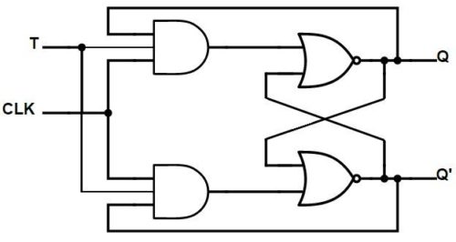
Internal Structure of T Flip-Flop
T Flip-Flop is usually constituted based on the JK Flip-Flop or D-Type Flip-Flop. Here are two examples of how these Flip-Flops can be used as T Flip-Flops:
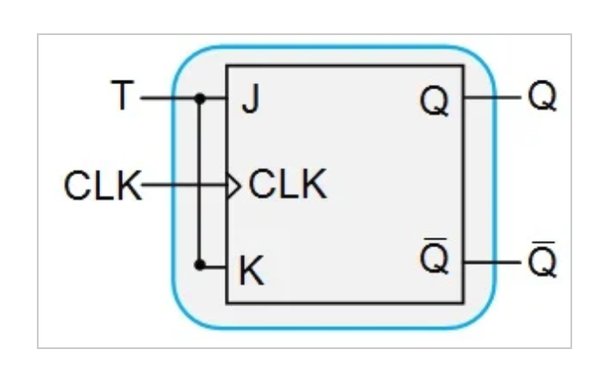
JK Flip-Flop and T Flip-Flop
A T Flip-Flop can be derived by connecting the J and K inputs of a JK Flip-Flop. Inputs J and K are connected to input T.
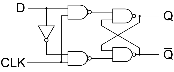
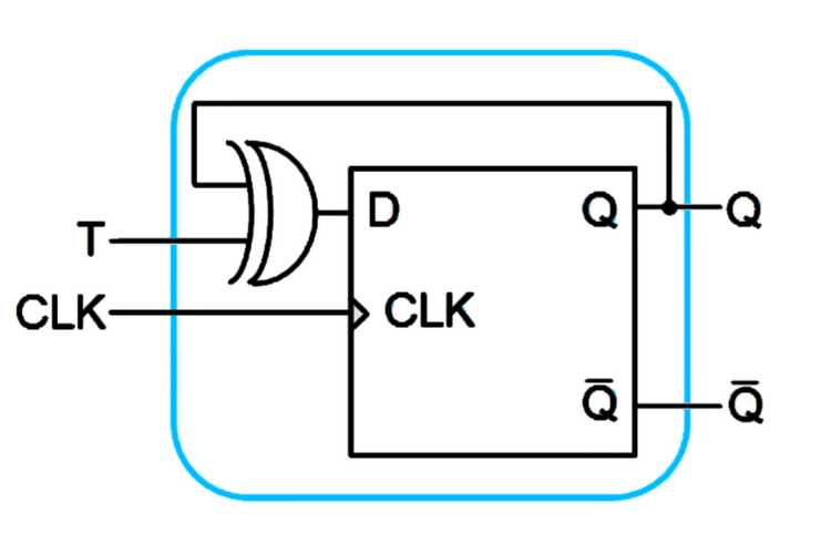
D-Type Flip-Flop and T Flip-Flop
T Flip-Flop can be derived by connecting the inverse function of the Q output to the D input of the D-Type Flip-Flop.
Working Stages
1. Initial State:
Initially when T = 0, the output Q maintains its previous state on the rising edge of the clock signal.
2. Toggle State (T=1):
When T = 1, the output Q toggles on the rising edge of the clock signal. If Q is initially 0, it becomes 1 and if Q is 1, it becomes 0.
3. No Change State (T=0):
When T = 0, the output Q maintains its previous state on the rising edge of the clock signal.
Areas of Application
T Flip-Flops are used in a variety of applications in digital circuits:
- Counters: T Flip-Flops are particularly used as the basic building block of binary counters.
- State Machines: They are used to monitor and control different states of circuits.
- Data Storage and Synchronization: They are used as simple data storage elements.